Our Door Opener (A Science Project)
Life in the labs has been pretty good since we moved into our current offices. Before, we were spread out over two floors: my team was upstairs in a stuffy law office sublet, and the rest of our colleagues were stuck in a homey but increasingly cramped and run-down space four floors below. Since moving everyone to the third floor we’ve found ourselves with plenty of room, lots more light and a nicer kitchen. It’s just a more pleasant working environment in general.
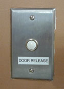 But there’s always room for improvement. For one thing, the new space came with new locks — ones with really expensive keys. Issuing keys to the entire staff wasn’t practical, and coordinating door-opening responsibilities in a way that accommodated team members’ occasionally odd schedules was inconvenient. Fortunately, the space also came with the button you see to the right. This button, with a few hacks, now makes it so we can open up our office with our Nexus Ones, iPhones or even SMS.
Located near the reception desk, this button opens an electronic latch on the front door. Pulling the assembly out of the wall revealed the system to be about as simple as possible: the button simply connects two wires. Bridging them with a screwdriver fired the latch (from their small gauge and uninsulated connections, it was obvious we weren’t dealing with dangerous voltages, but please don’t start pulling cable from your walls unless you know what you’re doing).
Connecting two low-voltage wires electronically isn’t a particularly hard trick, so I decided it’d be fun to spend some evenings building a system to expose that switch to our network. I’ve built a few projects in the past that make use of custom router firmwares and Arduino microcontrollers, so I decided to use those tools for the job. I’m a big fan of this approach — it’s a great, inexpensive way to add a scriptable network interface to your microcontroller projects (if you’re interested, I talk more about this technique here).
Ultimately, I ran into difficulty getting this particular router’s serial connection to work, so I abandoned the Arduino — it was overkill anyway. Inspired by the excellent new MAKE: Electronics book, I decided to build a circuit to do the job. Here’s the finished franken-router, hooked up to the switch:
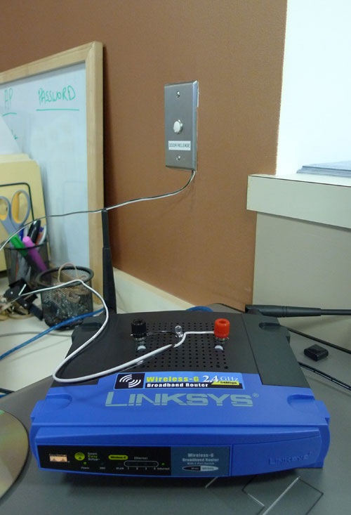
So how does this all work? Well, let’s start with the router. It’s a Linksys WRT54GL, a still-Linux-friendly descendant of the WRT54G, the router which jump-started the custom firmware scene. There are a lot of custom router firmwares available — DD-WRT, Tomato, Gargoyle — and they can all make your consumer-grade router do some professional-grade things. For this project I used OpenWRT, the system on which many of those other projects are based. It’s got a much steeper learning curve than those other distros — you definitely need to be comfortable with the command line — but it lets you build a custom firmware with exactly the components you want. With some tweaking I was able to create a firmware that included a stripped-down version of Python, but which still fit into the WRT54GL’s meager 2MB flash memory. (Like the Arduino, Python turned out to be overkill, but at the time I expected to need it — and it’s always nice to have it handy.)
With the firmware installed, I was able to SSH into the router and perform some simple manipulations of the system’s GPIOs — General Purpose Input/Outputs. These connect to things like the system’s LEDs and switches, and can be controlled in software. I selected a GPIO that didn’t seem to be used by OpenWRT — it illuminates the “DMZ” LED on the front panel — and wrote a very simple script to control it. I could now flip a tiny light on and off from a network connection. The hard part was over.
Next came the hardware. It was easy to add a pin header to the router’s PCB — it’s got holes drilled and ready to go (some of them are connected to router systems — see here). To this I hooked up ground, power, and a connection to one of the DMZ LED’s pins.

A cable then connects those three pins to this breakout board:

There are a few things going on here. That blue cylinder is a relay, and it’s the heart of the system. A relay is basically just a switch that can be closed by the electromagnet that’s attached to it. They’re useful for employing a small voltage to turn a larger voltage on and off. In this case, the switched inputs of the relay are wired up to the connection posts that I added to the outside of the router: when the relay is energized, those posts are electrically connected. When it’s not, they aren’t. The relay runs on 5 volts, which is why there’s a voltage regulator on the board: to reduce the router’s 12 volts to 5 (the other components on the board can run on a range of voltages; they’re perfectly happy at 5).
The router’s GPIO isn’t up to the task of controlling the relay directly, so there’s some additional circuitry that’s needed to turn the GPIO signal into a firing relay. First up: the 556 chip, which contains two 555 timer chips in a single package. When triggered, one of these fires the relay for a set amount of time — about half a second. The other timer starts up as soon as the circuit gets power, and stays on for almost half a minute. It’s responsible for disabling the first timer during the router’s boot sequence, when various scripts cycle the LEDs (and would therefore accidentally fire the relay and open the door).
You trigger a 555 by connecting one of its pins to ground, and at first I thought I’d be able to simply hook the GPIO up to the 555’s trigger. No such luck: this GPIO, at least, doesn’t go to ground when you switch it. Instead it changes between 2 and 3.3 volts (in between is the threshold where the LED happens to light up). The solution to this was to use a voltage comparator chip. This compares its input — the GPIO — to a reference value that’s supplied on another pin. In this case the reference voltage is 2.5 volts, made with an extremely simple voltage divider (basically just two equal-value resistors in series — the junction will be at half of the total voltage across them, which in this case is 5. Science!). If the input value is above the reference, it outputs a high value. If it’s below the reference, it connects its output to ground. So the comparator’s output gets connected to the 555, and voila! We’re done.
This is a pretty simple project, but I’m no electrical engineer, so it took me a while to get it working. But eventually I was able to use my SSH client to open the door latch. That’s not exactly an ideal interface, though: it’s both hard to use and hard to administer. I turned the problem over to my coworkers in the labs, and they built the rest of the system with amazing speed (and, it should be noted, in the middle of a blizzard). They’ve come up with some pretty impressive solutions — more on that in the next post!
UPDATE: I’ve been asked for a schematic of the door-opening circuit; here it is as an EAGLE .sch and as a simple PNG. If you do build this, a word of warning: the initial timer, which is meant to disable the system during boot, behaves somewhat differently in-system than it does on a breadboard. I’m still trying to address this issue — and have added a bypass capacitor to the schematic in an attempt to do so — but for us, it’s not a particularly pressing issue, as the vulnerability it represents is still substantially harder to take advantage of than it would be to simply smash down the door. Still, if you plan to use this circuit, please be aware of its limitations and understand that you use it at your own risk.